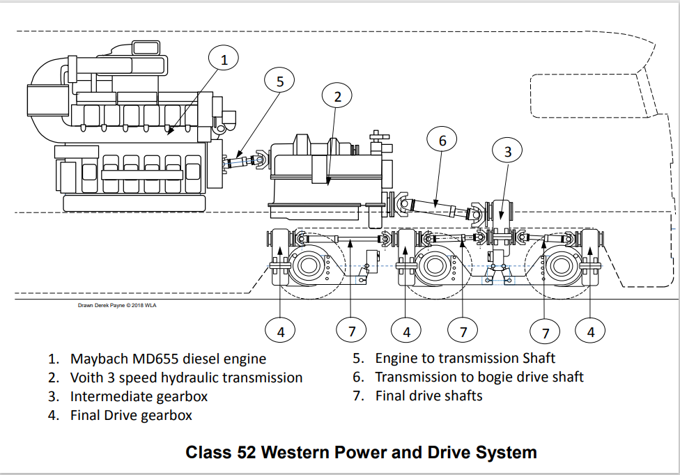
Western Class 52 locomotives were fitted with two engines each driving a separate transmission. The equipment was duplicated in each end. A schematic is shown below:
When running, the Maybach MD655 engine (1) rotates a cardan shaft coupled to the transmission (2). Using internal gears, two smaller cardan shafts mounted on top of the transmission rotate the dynostarter and hydrostatic oil pump (these are not shown). The dynostarter provides 110 volts for the electrical systems operating on the locomotive and acts as the starter motor for the diesel engine. The hydrostatic oil pump (not shown) works constantly and a small electrically operated valve diverts oil to the cooling fans to turn them as required.
When the driver selects "forward" (or "reverse") direction and then "notch one" on the power controller, the transmission (2) convertor 1st stage (gear) fills with oil and the diesel engine now begins to rotate this oil, rather like a ships propeller in water. Face to face with this "propeller" is another similar "propeller" which begins to rotate too and this is coupled to another cardan shaft leading to the bogie mounted intermediate gearbox (3). In this gearbox, a combination of bevel and wheel gears transmit the drive downwards. From there a cardan shaft (6) transmits the drive to the axle mounted final drive gearboxes (4). The locomotive will begin to move foward as soon as the brakes have been released.
As more power is applied by the driver (up to notch 9) on the power controller, the locomotive moves forward gaining speed and the converters within the transmission automatically change (1st to 2nd; 2nd to 3rd), each convertor decreasing in physical size until the 3rd convertor is used. This, the smallest of the three converters, then drives the train forward in the speed range between 63 and 90 mph.
The two locomotives owned by the Western Locomotive Association Limited are based on the Severn Valley Railway, which operates over 16 miles of track between Bridgnorth and Kidderminster. They are “Western” class 52 diesel hydraulics, D1013 Western Ranger and D1062 Western Courier. Both locomotives were retired from service with British Rail more than forty years ago.
The Western class are a historically and technically significant design as they replaced the famous King and Castle classes of steam locomotive on the former Great Western Railway in the 1960’s before being replaced in turn by the Inter City 125 High Speed Trains. Most of the seventy four locomotives were broken up for scrap, but seven survived, including the two WLA locos.
How does a Western Diesel Locomotive work?
A diesel engine works by internal combustion. Fuel is sprayed into the cylinders with air drawn in and the mixture compressed by a piston. If you compress a gas, it produces heat. In a diesel engine, this heat is sufficient to ignite the fuel, which explodes. Unlike a petrol engine, there is no sparking plug. This explosion produces an expansion of gases within the cylinder, which forces the piston down. The piston is linked to a crankshaft, which converts the up and down motion of the piston into rotary motion generating torque.
A Western has two 65 litre Maybach MD 655 diesel engines each driving a Voith hydraulic transmission which turn the wheels via a gearbox. The cylinders are arranged in a V formation driving a common crankshaft. The Maybach MD655 has twelve cylinders and produces 1380 hp at 1,500 rpm. Maybach diesel engines were also used in marine installations such as motor torpedo boats and fishing boats.
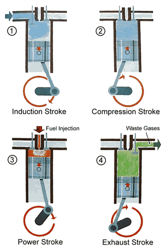
Maybach diesel engines operate on a four-stroke cycle; that is two up strokes and two down strokes. An inlet valve and an outlet valve are operated from a camshaft and control the air into the cylinder and the exhaust gas out.
The piston sequence is as follows:-
First stroke-Induction. This begins as the piston commences the down stroke with the inlet valve open. As the piston commences downward, it draws air past the open inlet valve into the cylinder. The exhaust valve is closed at this stage.
Second stroke-Compression. When the piston has completed the down stroke, the inlet valve closes, and as the exhaust valve is already closed, the air contained in the cylinder is trapped. The revolving crankshaft pushes the piston up and as it rises, the air trapped in the cylinder is compressed up into the combustion chamber. As the air is compressed it becomes extremely hot.
Third stroke-Power. With the valves still closed, fuel oil is sprayed through an injector into the top of the cylinder at the point of greatest compression and heat. The heat from the compressed air causes the atomised oil to ignite and greatly expand in volume. This forces the piston down the cylinder.
Fourth stroke-Exhaust. At the end of the power stroke, the exhaust valve opens and during the following up stroke of the piston the waste gases are pushed past the valve and out of the engine. The first photograph below shows the four strokes.
A turbo-charger is used in order to obtain the maximum power from the engine. This is a device which contains a turbine that sucks in air from the atmosphere and forces it into the engine through the inlet valve. The turbo-charger is driven from a turbine powered by the exhaust gases of the engine.
To keep the engines and turbo-chargers cool, the locomotive has large fans mounted in the roof. These draw air through the louvres in the body-side and through radiators mounted above the engines. The turning action of a diesel engine cannot be linked directly to the wheel. It has to be controlled so that the locomotive can start from rest with a train and cope with different gradients and loads. This is achieved on a Western by using a hydraulic transmission. Most locomotives nowadays use diesel electric transmission where the diesel engine turns a generator and the power produced drives electric motors, which turn the wheels.
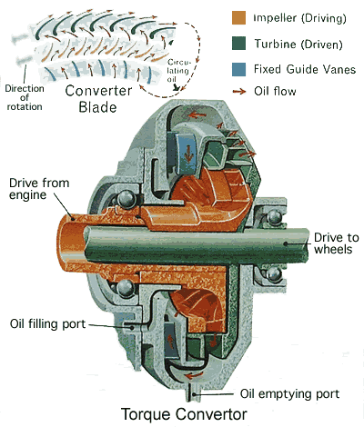
A diesel hydraulic locomotive has a torque converter, which is rather like a hydraulic pump revolving inside a housing filled with oil, which transmits power to the rails. It has three main parts, of which two rotate and one is fixed. Each part consists of a ring with specially shaped blades. The blades are curved to control the direction of the flow of oil. The three parts of a torque converter are the impeller (a centrifugal pump), the turbine wheel (or driven wheel) and the fixed guide wheel (or reaction wheel). The diesel engine drives the impeller and its power is passed on to the oil in the converter. The impeller blades pump the oil onto the turbine wheel blades, causing the turbine wheel to rotate. The turbine wheel is connected by a shaft to the locomotive wheels so when the turbine wheel rotates the locomotive wheels rotate. The second photograph below shows a hydraulic transmission.
The advantage of a diesel hydraulic system was its lightweight construction. Also the torque converter is so designed so that the lower the speed the greater the pulling power. A hydraulic drive also provides a shock free connection between the engine and locomotive wheels over the whole range of engine power.
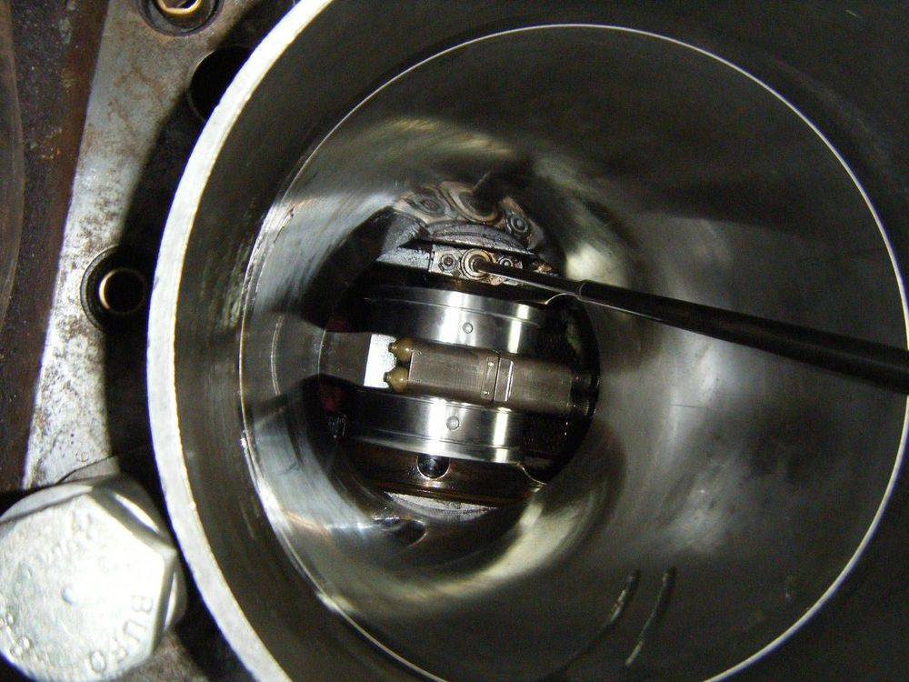
MD655 cylinder from below
Restoring a Western
Restoring a locomotive which is nearly sixty years old throws up problems, which at first seems insurmountable. The restoration of D1062 Western Courier was commenced in 1998. It had been repainted at Swindon Works in 1977 and had been the subject of a further light restoration in 1988. It was considered that the time had come for a detailed and thorough restoration. This involved cutting out all of the corroded metalwork and replacing it with new steel, completely rewiring the locomotive and thoroughly rebuilding both of the engines. When D1062 was given a test run however, a nasty grinding noise was found to be coming from the bearings in one of the transmissions. Voith who made the transmission are able to rebuild it and with the help of a grant from the Heritage Lottery Fund this hurdle was overcome.
The restoration of D1062 was undertaken by a dedicated group of skilled engineers working on a voluntary basis to the highest standards. D1062 was totally rewired and both of her Maybach diesel engines were overhauled incorporating modifications to achieve greater efficiency and to reduce emissions.
Now it is D1013 Western Ranger's turn and the restoration is well advanced with a total rewire completed and most ancillary equipment overhauled. Work has begun on the engines and bogies and we hope to complete the overhaul next year in time for her 60th birthday
The WESTERN LOCOMOTIVE ASSOCIATION is a company limited by guarantee - Registered No: 3873466 Registered Address: 5, Prospect Place, Millennium Way, Pride Park, Derby, England DE24 8HG. Charity No. 1115058
We use cookies to ensure that we give you the best experience on our website. If you continue to use this site we will assume that you are happy with it.